Cache Design in Multicore Architecture
Cache Organization
Physical and Logical Cache Organization
Physical cache organization refers to the actual hardware arrangement of cache memory in the system. It determines how cache units are physically placed relative to the processors and main memory.
- Physically united:
- Features: It's Single Central Cache. All processors share a single, centralized cache memory unit. The cache is located at a central point accessible by all processors.
- Advantages: Hardware design is simplified due to the centralized nature of the cache. With only one cache, maintaining coherence is straightforward.
- Disadvantages: The central cache can become a contention point as multiple processors attempt simultaneous access. Processors farther from the central cache experience higher access latencies. It has limited scalability.
- Physically distributed:
- Features: Each processor has its own cache physically located close to it.
- Advantages: Proximity of cache to processor minimizes access time. Systems can scale to a larger number of processors without a central bottleneck, it has good scalability. Local caches provide faster access to frequently used data.
- Disadvantages: It requires mechanisms to ensure data consistency across caches. The same data may be stored in multiple caches, increasing memory overhead.
Logical cache organization pertains to how the cache system appears from a programming and operational standpoint, regardless of the physical arrangement. It defines whether the cache is shared among processors or dedicated to individual processors.
- logically shared:
- Features: Shared address space among cores. There are mechanisms that maintain data consistency across cores.
- Advantages: Ease of programming, simplified programming model.
- Disadvantage: There will be coherence issues which will cause coherence overhead. Coherence mechanism also becomes bottleneck as the number of processors increase.
- logically private:
- Features: Private address space, need explicit data sharing (limits shared memory programming model). Changes made by one processor is isolated in the view of other processors.
- Advantages: No need for coherence protocols. Processors are insulated from each others' behavior, which reduces contention.
- Disadvantages: More programming complexity (need explicit data sharing). Same data might be stored in multiple caches, which cause redundancy.
Combining Physical and Logical Configuration
- Physically United, Logically Shared
- Single central cache, unified view, use as is, suitable for small scale multiprocessors
- Ease of coherence, but becomes bottleneck under heavy load, scalability is limited.
- Physically United, Logically Private
- Single central cache, but private accessed by each processor
- This is strange... does anyone who use this?
- Physically Distributed, Logically Shared
- Each processor has a local cache, which is a part of a logically shared cache memory space.
- Coherence protocol is needed. This is commonly used in modern multiprocessor and multicore systems.
- Physically Distributed, Logically Private
- Each processor has its own cache, both physically and logically isolated.
- It requires explicit data sharing between processors. This is suitable for distributed systems and cluster computing.
Shared Cache on Physically Distributed Cache
Different organizations based on different physical architecture:
| Name | Crossbar switch | Tiled Multicore | Shared bus | Multistage interconnection network |
|---|---|---|---|---|
| Illustration | 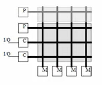 | 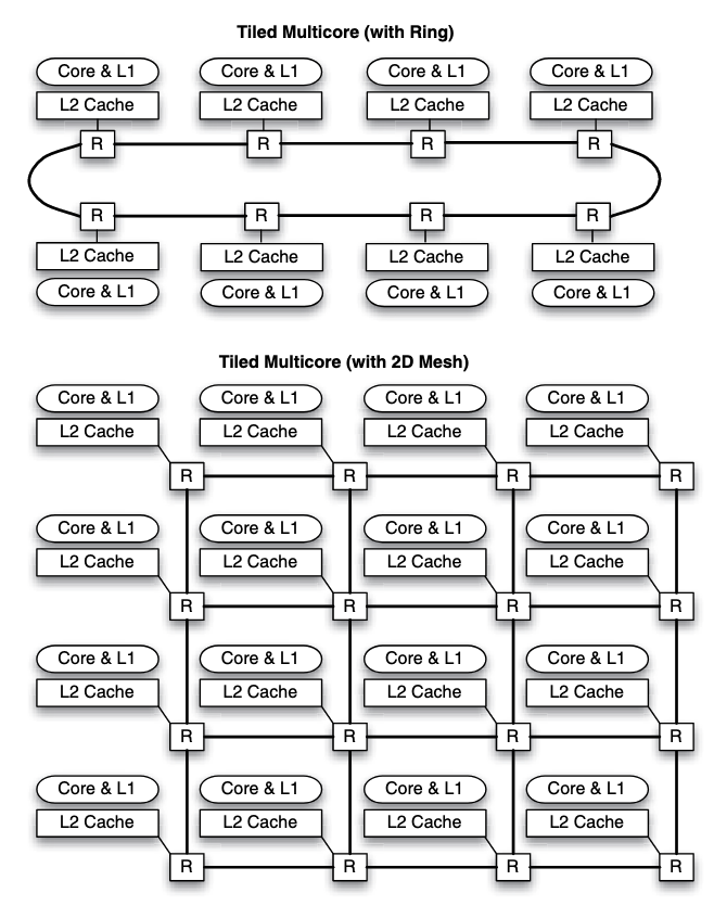 | 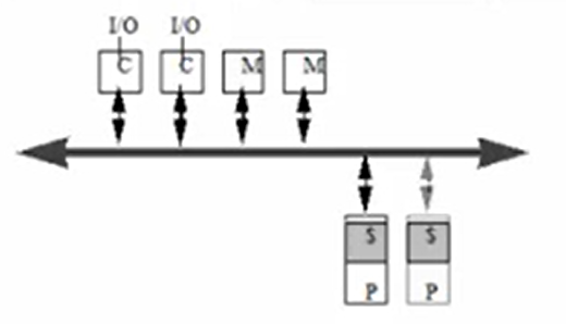 | 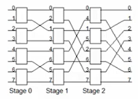 |
| aka | the inerconnection structure | symmetric multiprocessors(processors have the same priority accessing the bus) | ||
| Discription | Each processor has a direct connection to each memory and IO controller | All processors, memories, and IO controllers are connected to the bus | Its a compromise between these two organizations. The processors are on the one side and memories and IO controllers are on the other side. | |
| Bandwidth | Bandwidth scales with the number of processors | The total bandwidth remains the same when the number of processors scales up | It allows more parallel transactions than a shared bus but unlike a cross bar switch, there is still a chance of contention between two transactions. | |
| Cost | Cost scales with the square of the number of processors | Cost scales linearly with the number of processors(lower incremental cost than cross bar switch) | Cost depends on the number of stages and the width of each stage. The number of stages depends on the number of processors and memories. | |
| Shortcomings | When the number of processors scales up, the costs of the cross bar switch becomes the big component of the whole system, which is not cost effective. | Latency lager than uniprocessor, but bus could become bandwidth bottleneck when the number of processors becomes large. When the bus is being used by another process, one process could stay waiting and trying to access to the bus which could cause huge overheads. | It has the same shortcomings as the two before, and its not easy to be scaled up too. |
caches in crossbar configuration is not necessarily called banked cache. It could be banked in logical manner.
United Cache Organization
In the IBM Power4 chip, a crossbar is used to interconnect cores with cache banks.
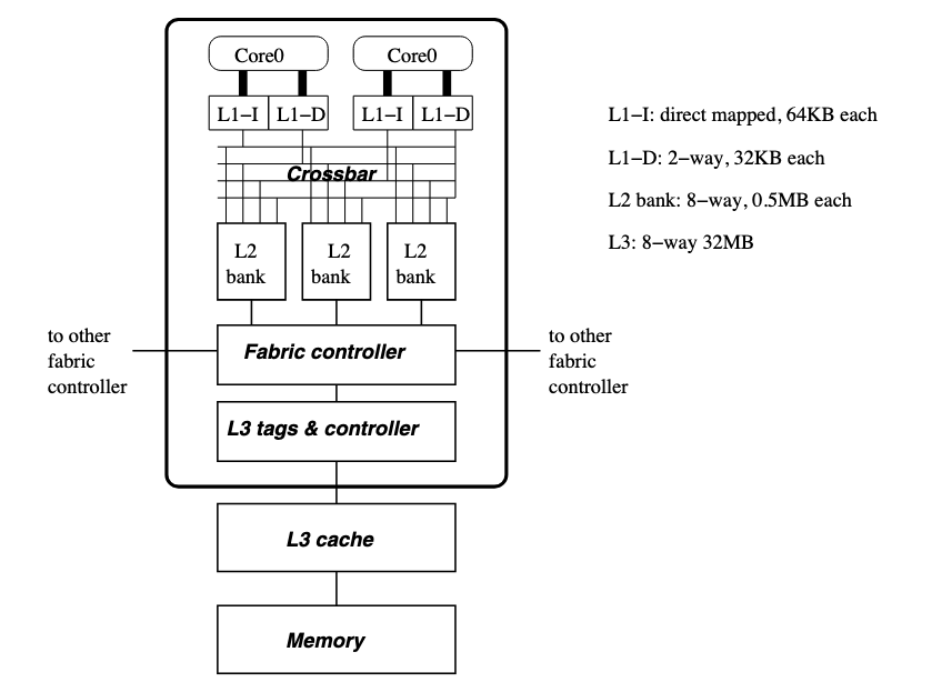
Crossbar allows cores to access different banks simultaneously. Only when two cores access the same bank, their accesses collide and have to be serialized. However, it allows concurrent access from multiple processors to separate cache banks. The performance of applications improves when the cache is broken into smaller banks, allowing the applications to access cache banks that are close by with a low access latency; only accesses to far-away cache banks incur a high access latency.
Scaling the crossbar to many cores will essentially reduce the die area available to implement the cores themselves and the cache. In addition to the complexity of providing a crossbar, a large united cache suffers from a high access latency, due to the physical length of wires that form the cache structure (e.g., word lines, bit lines).
Distributed Cache Organization
a convenient and logical way to scale a multiprocessor system is to move the interconnection down the memory hierarchy. In this case, multicore architectures will likely implement physically distributed L2 caches that are connected using an interconnection network or backed up by a united L3 cache.
Logical Cache Organization
Cores are logically connected to cache tiles in some way, and they are actually physically connected(via interconnection network etc.) The important concept here is distance locality, which is feeble for a large multicore system (since it's quite far away from the core to the farthest cache tile)
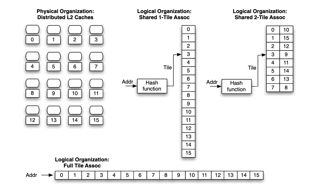 For a tiled multicore, a hash function determines which tile the address maps to.
In the figure, if the core that accesses a data block is core , and the data block maps to tile , the network distance (assuming a two-dimensional mesh) is hops. To get a message across, each router likely introduces at least a 3-cycle delay, corresponding to the number of pipeline stages implemented in the router.
For a tiled multicore, a hash function determines which tile the address maps to.
In the figure, if the core that accesses a data block is core , and the data block maps to tile , the network distance (assuming a two-dimensional mesh) is hops. To get a message across, each router likely introduces at least a 3-cycle delay, corresponding to the number of pipeline stages implemented in the router.
Higher associativity can be introduced to improve distance locality. For the example above, using a -tiled associated cache with tile and tile in a set, tile and tile in a set etc., which makes the average distance between the core and cache tile closer.
However, there are drawbacks to tile associativity. The higher the associativity, the more tiles must be checked simultaneously to locate a data block. This consumes additional power, as well as incurs a higher network traffic compared to a single tile-associativity.
Such drawbacks can be mitigated to some extent by requiring a core to look up the closest tile in a tile set first, and look up farther tiles only when the block is not found on the closest tile.
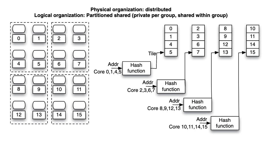 Figure: Hybrid private and shared configuration, a tradeoff between distance locality and capacity. Cores closed to each other are grouped to use shared organization and cores between groups are privately managed.
Another way to think about this is to consider cores in a group share cache with associativity. For the figure on the left consider each group of cores share a 4 ways cache and there are 4 sets. While this is not accurate, it provides somewhat insights understanding the tradeoff.
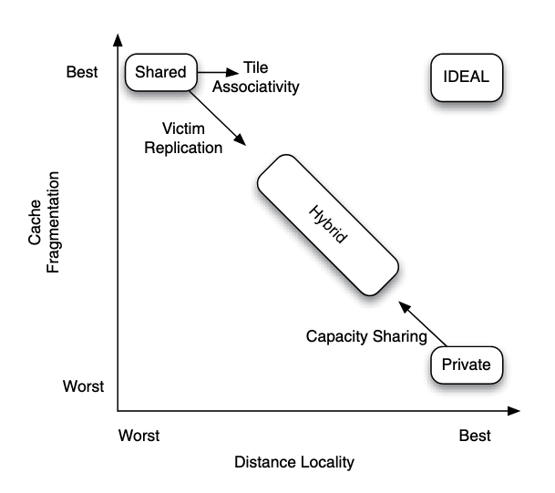 Figure: Comparing the merits and drawbacks of logical organization choices for distributed caches.
There are two extremes:
- If an application running on a core has a working set that exceeds the local cache tile size, the application will suffer from a high number of capacity misses.
- On the other extreme is the shared cache configuration. It has the best (or least) cache fragmentation because each processor has access to the aggregate cache capacity. However, data may be spread out over many tiles, meaning that data is on average far away from each processor. Hence, it has the worst distance locality.
In between the two extremes is a hybrid configuration. The key thing here is to find the balance between capacity and distance locality.
Hashing Function
A hashing function maps a block to a cache tile or to a tile cache for a shared cache organization.
Important problem here is called block interleaving and page interleaving, which means unaligned mapping from block memory address to cache location:
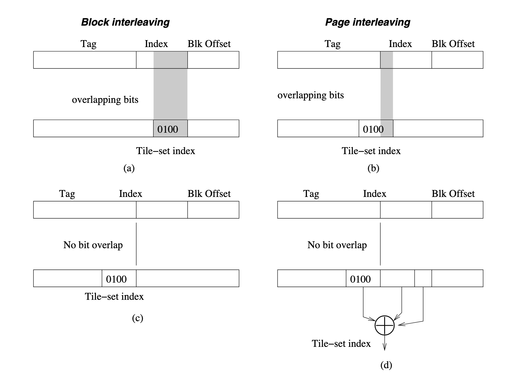
Figure: Bad tile hashing function due to block interleaving (a) and page interleaving (b), an improved hashing function (c), and an improved hashing function with bit randomization (d).
Improving Distance Locality of Shared Cache
Some techniques that improve upon the shared configuration:
- Victim replication (reduces aggregate cache capacity but improves distance locality)
- Capacity sharing (reduces cache fragmentation at the expense of distance locality)
Victim replication is an attempt to improve the distance locality of shared cache configuration by allowing blocks mapped to a remote cache tile to be replicated in the local cache tile. Specifically, blocks evicted from an inner cache (victims) may be temporarily cached in the local cache tile.
Capacity sharing allows blocks evicted from the local cache tile to be allocated to a remote cache tile. Later, when the processor requests for the block again, it can find it in a remote cache tile rather than having to fetch it from an outer memory hierarchy level.
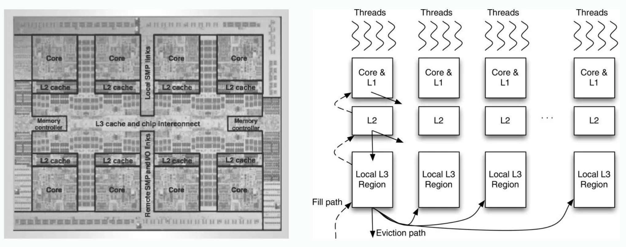 On IBM Power7:
- L1 cache is private to cores, when eviction happens, it will go away.
- L2 cache is private to cores, when eviction happens, it will go away or move to outer L3, its victim replication.
- L3 cache is shared, when something is evicted from a location in some local L3 region, it will go away or go somewhere else in another local L3 region. Its capacity sharing.